Let's be clear, I know nothing at all

"You Will Never Walk Alone"
Showing posts with label Engineering Work.. Show all posts

Monday

ASV RC50 - Bucket Cradle + Cylinder Pins and Bushes.

 PHASE TWO - Replace pins and bushes.


This is the bucket cradle - all the bushes worn out and pins shot.

We machined new bushes to suit - bored them to size and welded into place.


Bushes welded into place and then reamed to suit the new pins.


Pins slide into new bushes, all ready for assembly.


Like Hannibal says " I love it when a plan comes together."


Now we start on the worn out bucket cylinder rams.
Both side are worn beyond repair.


And so we have a plan.
for the rod ends we will fabricate new bushes and weld them onto the rods 
after removing the old ones.

Easy said!  Of course.!!

4 x round bar ready to be machined on the lathe.


Ready to be welded onto the rod ends.


Next we execute the old rod bushes - leaving the rod only.


We prep the steel for a low hydrogen weld and coat the rod with anti-splatter.


The executed rod end and the cylinder ends.


A patient weld - and the rod end bush is mated to the rod.


Next is the cylinder ends on the bucket cylinders.
Here the plan was to machine the worn-out hole larger and press fit a new bush into place.


Worked like a dream.
New bush - New pin.


For the load arm cradle cylinder ends we had a challange.
They wee so worn that there was not enough meat to machine a bore for a new bush.
So after execuing the cylinder ends we came up with this plan.

Two eyes were machined on either end of a lenght of flat bar.
These were then machined off and welded to the cylinders.


The machined eye - ready to be welded to the cylinder.


Job done! Eye welded into place.


Only thing left is to hone the cylinders before assembly + fit new seals.


All assembled and back on the machine.
Ready for the next few years of hard work.


Top-end of the bucket cylinders.


Bucket cradle all assembled and in place.


Saturday

ASV RC50 - Pins and Bushes on the Cradle Arms.

 RC 50 ASV Skid Steer Loader has a very worn set of pins and bushes.

This week starts off with removing the cradle and replacing all the pins and bushes.


Here is a clip of the free play between the pins cradle bushes.


Check the slop in these bushes.


The RC50 has had the bucket arms and cylinders removed - 


Ready to remove the loader cradle.


And off come the cradle - now we inspect the damage.


Many years of hard work and abuse and this pin is worn-out.


Chech the wear in the bush - more than egg shaped.


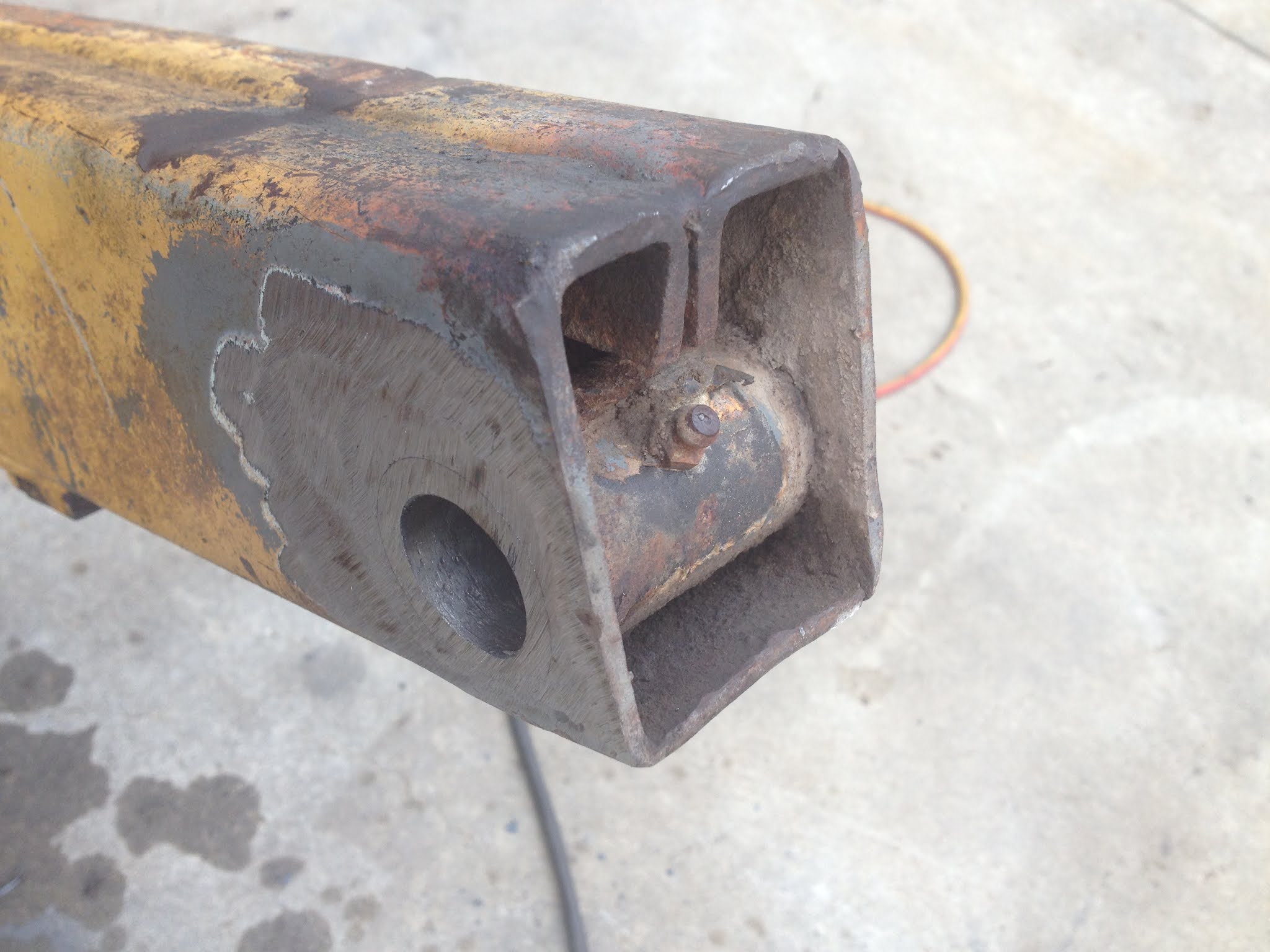
The hydraulic ram is not much better - here the eye has retired.


We start removing the old bushes by grinding away all the welding with the trusty 9"


A little more tricky this one - Not at all , just a mild challenge.


Notice the internal webbing, welded to the bush!
How do we tackle this?


Now the web is free from the bush!


Next we drive out the old bush -


Ready to accept the new Terex bush.


This is the genuine bushes supplied by the manufacturer.


Slid into place and ready for the weld.


Great fit Buddy!


And so the welding begins, the fun part.


We have folded a flat bar around the front of the arm and welded it up
in a bid to strengthen and support the bushes.
Worked like a dream.


Cradle bushes welded into place.


End Side of the cradle, capped off to strengthen the arm.


This is what the job looked like after assembly.


The top view of the bucket bushes and the shiny part is the new perches made for the cylinders.
Read bbout this watr of the job in the next post.


Maxlilf 130D Crane Truck Fit Out.

 This splendid Mitsubishi UTE presents itself for a crane installation.


Customer   -   +ONE Hoists.

The Maxilift 130D crane has a lifting capacity of  990kg at 1.1m.

  1. All the hydraulics are powered from a 12Volt power pack that forms part of the control-box.
  2. A good solid power line from the HD battery in the engine bay was required to supply power to the hydraulic power-pack. 
  3. As the crane needs to be mounted as far back as possible, a sub-frame is required.
  4. To keep the lift safe, a set of outriggers were also designed and fitted to the exercise.


The crane arrives on the back of the UTE.


First thing that needs doing is remove the load tray..


Maxilift 130D crane with a lifting capacity of 990 kg at 1m   or   300 kg at 3.8m


Design and installation of the rear sub-frame onto which the crane is mounted.


Notice the 4 x round posts on the righthand side of the pic, that's the mounting pedestals for the crane.
They protrude through the load tray and the crane is bolted down onto the pedestals and not the load-tray.


Gussets welded into place to prevent the sub-frame from moving while in transit.


Fabrication begins on the new look rear bumper bar.
Housed in it will be the legs of the outriggers.


Prep and weld old boy!


Completed rear bumper come outrigger bar.
Ready to be bolted into place and strong enough to stabilize the load.


The control box that houses the hydraulic pump and overload sensors.


Job completed - load tray fitted - crane fitted - hydraulic pump fitted - pump wired up - 
outriggers fabricated - bumper-bar fitted.


The outriggers were made to extend out 700mm each - this would
 make the crane more stable under load. 


This crane receives a service when due, here are some shots of her after some 
years of hard work installing hoists all over Melbourne.


All stowed away, safe and sound.


And here we are, doing what we were designed to do!


Click on the image below to visit and contact George at +ONE Hoists.